In September 2018 I built a remote receiving station for the SatNOGs project. This post describes the build process, and modifications I made to allow for coax power of a Mini-circuits ZX60-33LN-S+ low-noise amplifier.
SatNOGs is a distributed ground station network for amateur radio and university satellites. The idea is to spread a bunch of software-defined receivers around the world to help satellite operators downlink more data from their satellites. The open-source project, running on your local hardware, controls a software-defined receiver, moves directional antennas if you have them, and uploads the audio files and decoded data to a big database. Satellite operators, and other curious people, can see almost-real-time telemetry from the satellites.
As a historical aside, the concept of CubeSat teams sharing ground station resources has a long history, starting back with the first CubeSats launched in June 2003. Here's a partial list of CubeSat-specific networks that laid the foundation for the SatNOGs network:
- Professor James Cutler, from Stanford and now University of Michigan, built the Mercury Ground Station Network for commanding the Stanford QuakeSat CubeSat. Presentation.
- Japanese universities, led by the University of Tokyo, built the GSN to support Japanese CubeSats. Cal Poly State University joined the network in 2006, when I was a student. This network eventually grew to 12 Japanese universities and 4 international universities.
- ESA Education saw the success of GSN and decided to build an open-source European network called GENSO. Cal Poly and some Japanese universities joined, and a lot of software was written, but the effort collapsed (before any passes were actually taken) when ESA lawyers got involved.
- Over in England in 2009, AMSAT-UK started the Funcube-1 CubeSat as an educational project. To get the telemetry down, they designed and built a very low-cost ground radio from a TV tuner chip, and then built a internet data warehouse to collect this decoded telemetry. This network is still running today.
- After I graduated, Cal Poly built SatNet for communications with their CubeSats.
SatNOGs came out of hackerspace.gr in Greece in mid-2014. That same hackerspace was building the UPSat CubeSat for the QB50 project, which was planning on using GENSO to downlink their data. When GENSO collapsed, the team needed another way to get their data down, and SatNOGs was born.
With the price of SDRs and computers being so cheap nowadays, I thought it would be fun to build a station and contribute back to the community.
SatNOGs Station Build
I decided to build an omnidirectional station, without any moving parts. Since this station was going to live at a remote location (I don't have roof access at my current home), I didn't want to deal with cables snagging on things, motors breaking, things falling down, etc. Moving parts eventually break.
This also meant that this station would be limited on what it could receive; with a limited gain antenna, lower transmit power or higher data rate satellites wouldn't be received. The receive performance of RTL SDRs also leave a lot to be desired, as these devices are designed for receiving DVB-T signals, which are really strong.
Since I didn't want to add directional (gain) antennas, was there another way to increase the system performance? Receive system performance is measured using a figure of merit called antenna gain-to-noise-temperature (G/T). G/T is a simple concept, it's basically a ratio of system gain over noise temperature, but the actual measurements are a bit complicated and math-heavy.
A bigger G/T number means better signal to noise ratio. To get more SNR, if you can't increase the gain of the system (numerator), then reducing the system temperature (denominator) is your only option. What was the noise figure of the RTL SDR receiver? The specified noise figure of the RTL SDR is around 4 dB, but in real life it's anywhere between 6 and 20 dB, which is pretty bad! It's going to be difficult receiving weak signals from a distant satellite.
However, system temperature is mostly set by the first active device in the receive chain. So we can cheat a bit and increase our G/T number by inserting a lower-noise device ahead of the receiver. I had a few Mini-circuits ZX60-33LN-S+ low-noise amplifiers laying around, with a specified noise figure of around 1.1dB, or about 84 Kelvin.
If you're interested in learning more about system noise temperatures, link budgets, and satellite communications in general, I highly recommend playing around with Jan King W3GEY's link budget spreadsheet. It goes into great detail about all the aspects of the link budget, and you can see exactly how the LNA's overall gain is less important than the noise figure.
I gathered up all the components for my station:
- RaspberryPi Model 3B, which was the best at the time
- RTL-SDR Blog v3 Dongle
- Mini-circuits ZX60-33LN-S+ LNA. 20dB gain, 1.1dB noise figure (now EOL; replacement part is ZX60-33LNR-S+)
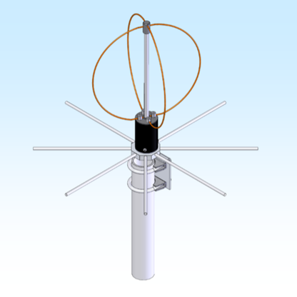
- M2 EB-432/RK70cm eggbeater antenna, 400 to 470 MHz
- Waterproof plastic box with wood mounting plate inside and unistrut channel on back
- PoE Splitter for powering the RaspberryPi
- Real IEEE 802.3af power PoE power injector
Here's a block diagram of the system:
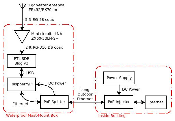
The entire station is powered via Power over Ethernet (PoE), which is a IEEE standard that uses some of the spare Ethernet wires for power. The PoE splitter powers the RaspberryPi, which powers the RTL SDR dongle via USB. The only other active component here is the LNA, which will be powered via coax from the RTL SDR dongle's internal bias tee.
Bias Tee LNA Modifications
The one problem with powering the Mini-circuits LNA through the coax cable is that this LNA doesn't accept power this way. It requires DC power on two power pins external to the LNA. I thought about buying a bias tee to pull power from the coax cable, but I'm cheap and those devices are cost more than the RTL SDR dongle and RaspberryPi combined. Could I modify the LNA to accept power from the coax cable?
A bias tee is fundamentally a diplexer, which is basically a frequency-selective splitter: one set of frequencies (0 Hz, or DC power) is pushed to one port, and another set of frequencies (400 MHz, or 1 GHz, or whatever frequency you build it for) get shunted to another port. Bias tees are useful for powering remote devices, such as a LNA at the end of a long coax cable. Bias tees are bidirectional, which means you can either combine power and RF signals onto a single coax cable, or split the power and RF signals onto different ports.
The Mini-circuits ZX60-33LN-S+ is a 50 to 3000 MHz broadband low-noise amplifier. At 450 MHz, the gain is approximately 21 dB with a noise figure of 1.0. Power requirements are 3 to 5 Volts, approximately 70 mA, from a stud on the side of the case. I decided to open up the device and see if there was a way to power it from the coax cable.
Unfortunately, Mini-circuits does not publish schematics of any of their components. So I started poking around, making voltage measurements with the device powered, and resistance/capacitance measurements when off.
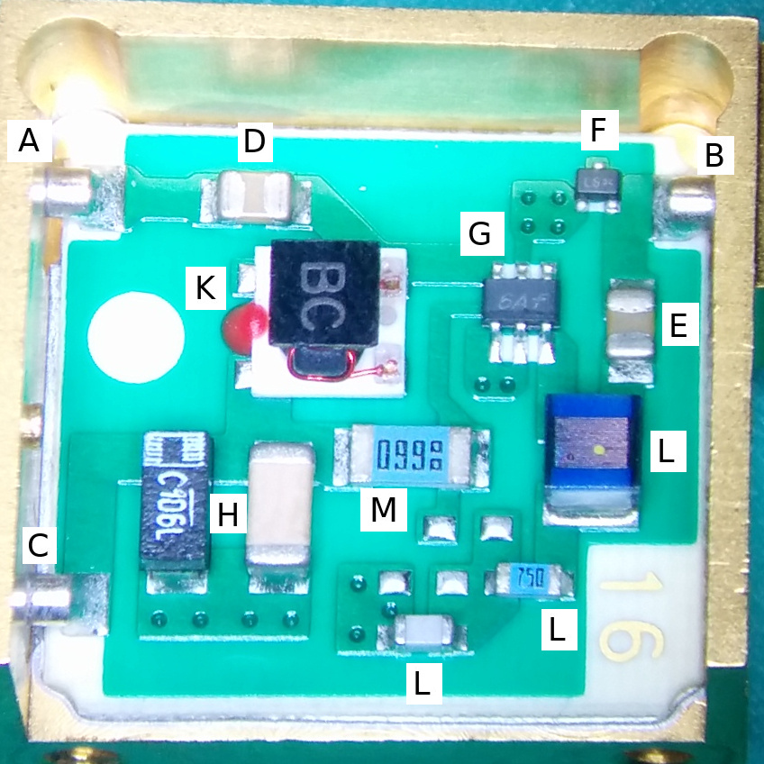
Here's my "10+ years out of college" circuit analysis of the device, without any destructive testing:
- Port A is the output port. This is connected to the radio, and where I want the 5 V to come in.
- Port B is the input port. Connected to the antenna.
- Port C is where the DC +5 V normally comes in. DC ground just goes to the case, and probably the bottom layer of the PCB.
- Capacitor D is probably a DC-blocking capacitor on the output. This capacitor prevents stray DC on the output port from affecting the amplifier, and also to prevents DC power from leaking out on the output port.
- Capacitor E is another DC-blocking capacitor on the input port.
- Component F is probably a protection diode of some sort. Max input to the LNA is +13 dBm, so if more power is put into the LNA it probably gets shorted to ground.
- Integrated circuit G is the actual LNA chip. Not sure what the part number is. Input is in the lower right, and output is in upper left.
- Both H capacitors are probably decoupling capacitors, smoothing out any noise present on the DC input line.
- Inductor K puts +5 V on the trace that leads to the output of the LNA chip. The LNA chip is probably powered from this.
- The three L components look like an RLC circuit, connected to the input of the LNA chip. This is probably for a filter for the input. Or maybe it's a matching circuit, if the input to the LNA chip is not 50 ohms?
- I'm not sure what resistor M does, maybe some sort of power circuit for the LNA chip?
DC-blocking capacitor D gives me an great way to prevent DC power on the output port from affecting the LNA operation. If I can put an inductor from the input port to the DC power port, I can power this thru the coax.
This inductor must pass DC (which all inductors do, as they are just lengths of wire), but block RF frequencies, so the amplified RF doesn't feed back into the LNA. Searching the Coilcraft website for "Bias Tee," they have several options. I chose the 4310LC series.
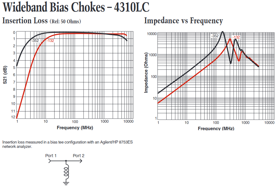
Looking at the specifications, the first graph (and schematic directly below the graph) shows that frequencies less than 10 MHz pass thru the inductor (to ground in this case, showing a lot of loss. This is what we want). Frequencies from about 10 MHz up to 6 GHz pass from Port 1 to Port 2.
The second graph shows the impedance (AC resistance) versus frequency. Higher is better. Since I'm building this circuit for 437 MHz, I selected the -352 variant, which shows about 4 kOhms impedance at that frequency, which is much higher than the -132 variant. Getting the parts from Coilcraft was painless, you can sample up to 10 for free!
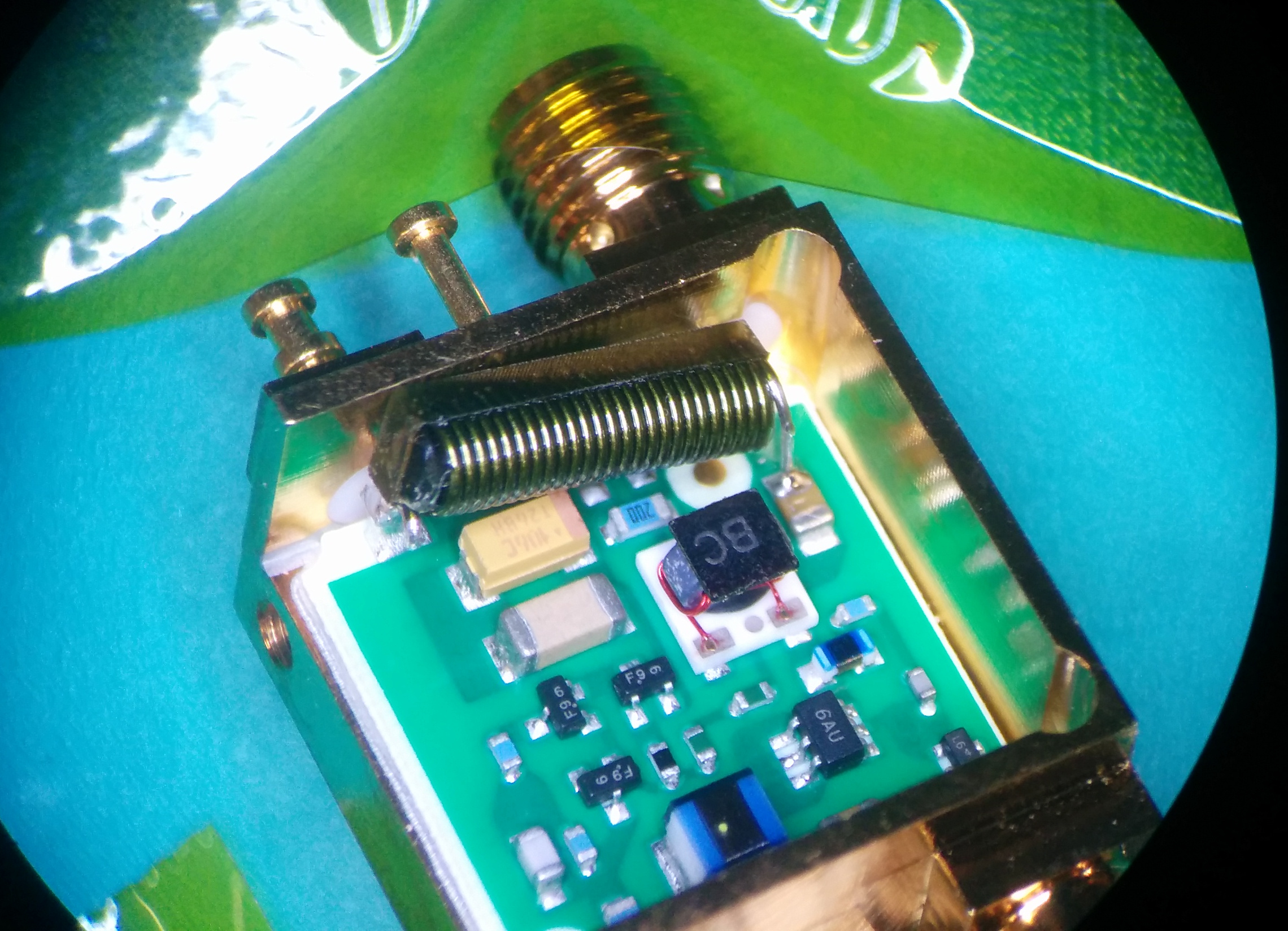
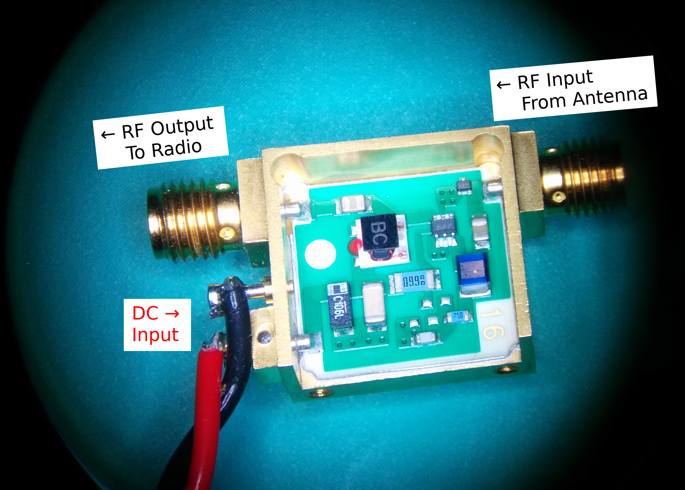
Here's the final product. Because of the shape, I soldered the 4310LC-352 inductor between the power port stud and the output DC-block capacitor. It fits nicely! There's even some epoxy on the back side of the inductor that prevents it from shorting against the case.
Notice that this LNA has a different PCB, although all the main components are the same. I guess something changed and Mini-circuits needed to put out a new revision. Testing the LNA before and after this modification showed that the gain and power consumption was the same as before modification. Success!
Antenna Selection
There are many options when it comes to antennas. I thought about making my own 1/4 wave ground plane antenna. They work pretty well for terrestrial use, and they are very cheap and easy to make. But since they are linearly (vertically) polarized, and have a radiation pattern null straight up, they aren't great antennas for spinning/tumbling satellites. 5/8 wave and higher-gain antennas just push the radiation pattern closer to the ground, which is not good for receiving satellites going overhead.
Another option is building a Parasitic Lindenblad antenna, this one designed by Tony AA2TX (SK). Built out of PVC pipe, it has a bit of gain with a circularly polarized radiation pattern. Other antennas I could build were turnstile and eggbeater antennas.
In the end though, I realized that this project was about receiving satellites, not building antennas. I searched online, and settled on the M2 EB-432/RK70cm eggbeater antenna from M2 Inc. This eggbeater is vertically polarized near the horizon and transitions to circularly polarized straight overhead. Since it's an omnidirectional antenna, the gain isn't much.
Putting It All Together
After getting all the parts and testing them separately and together, I started putting everything in the waterproof box.
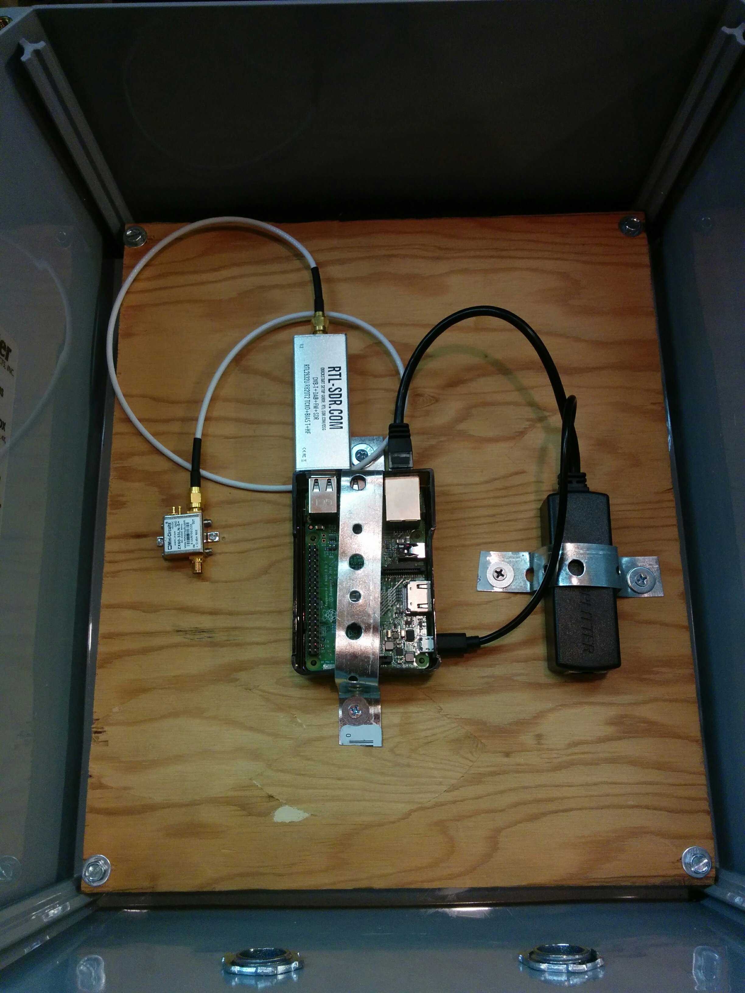
Lots of extra room! As for the software installation, I just followed the Omnidirectional Station How To. One thing that needs to be configured, beyond just the regular lat/long/API key settings, is the pre-observation script that turns on the LNA before a pass. The rtl_biast (see Feature 2) program needs to be built, and these commands added to the configuration:
SATNOGS_PRE_OBSERVATION_SCRIPT: /home/pi/rtl_biast/build/src/rtl_biast -b 1
SATNOGS_POST_OBSERVATION_SCRIPT: /home/pi/rtl_biast/build/src/rtl_biast -b 0
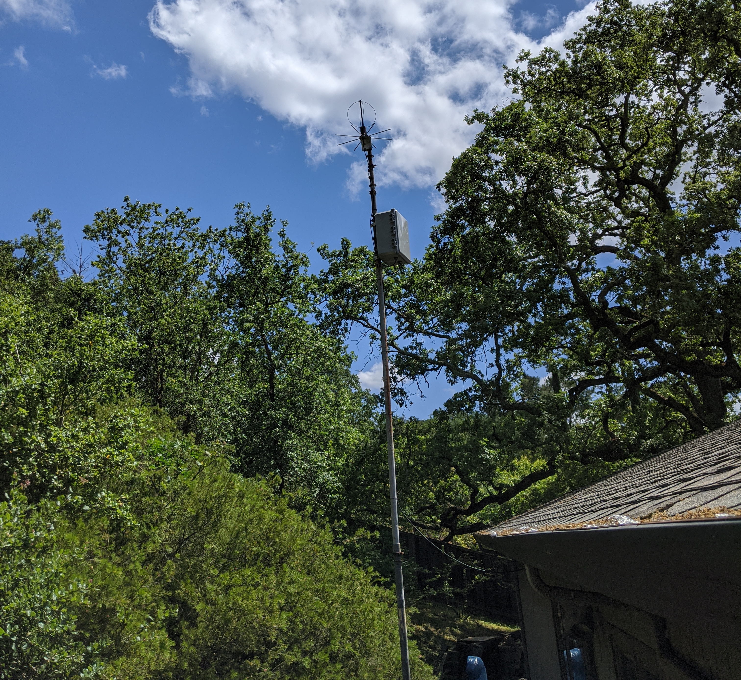
I installed it at my parents house, and it's been working for the past two years with no issues. I was worried about the heat of the components inside a fully enclosed box during the warm summer months, but there has been no problems so far.
See the station on the SatNOGs website.
Future Upgrades and Changes
If I were to do this project again in the future, there are a few changes that I would make:
- RFI Mitigation: I haven't measured it, but I'm sure that the RFI noise from the PoE splitter and the RaspberryPi is pretty horrendous. The PoE switching supply that that takes the 50v DC and bucks it down to 5v DC is probably the worst offender. I would add ferrite cores on the long Ethernet cable (to prevent radiated emissions), and also on the short Ethernet and micro-USB cables from the PoE splitter to the RaspberryPi. A Ham's Guide to RFI, Ferrites, Baluns, and Audio Interfacing is a great resource for RFI mitigation.
- RTL SDR noise mitigation: There is probably a lot of noise from the RaspberryPi that leaks into the RTL SDR dongle thru the USB power and data pins. I would fix this by separating the RaspberryPi and RTL SDR dongle with a short USB extension cable (thick-gauge to keep cable power losses to a minimum), and wrap some ferrite cores around that cable.
- Separate the antenna from the electronics. Any radiated noise from the RaspberryPi travels up the coax shield and is received by the antenna and amplified by the LNA, causing problems. I put my receiver box up at the top of the mast, so coax losses would be minimized. However, it's probably smarter to have a few more tenths of a dB of coax loss, and 10 dB less noise coming into the LNA and receiver. Adding ferrites on the outside of all coax cables would also help.
- Would a RF filter help? I'm not sure about this. The nearest cell towers are about 500 meters away, and there are no broadcast transmitters within several miles. There is some wifi nearby on both 2.4 GHz and 5.8 GHz, but those frequencies are much higher than the UHF amateur satellite band. The LNA is not going into compression, and putting the filter in front of the LNA would reduce receive sensitivity by 2 or 3 dB.
Further Reading
- Jan King W3GEY's link budget spreadsheets. Very detailed link budget spreadsheet, it's great to play around and see how different parts of the receive/transmit chain affect the RF link. (local copy)
- Evaluation of SDR Performance. Includes the RTL SDR Blog v3, Airspy Mini, LimeSDR Mini, and several others. (local copy)
- Coilcraft application note that talks about selecting the right inductors for bias tees. (local copy)
- Determination of Earth Station Antenna G/T Using the Sun or the Moon as an RF Source, by Michael Morgan. A great paper from the SmallSat 2018 Conference about measuring G/T on small dishes. Not really applicable here, but very interesting nonetheless. (local copy)
- Information about RFI from the ARRL.
- A Ham's Guide to RFI, Ferrites, Baluns, and Audio Interfacing by Jim Brown K9YC. (local copy)