Now that Solar Cycle 25 is upon us, I wanted to get active on the HF bands. My primary bands of interest are 40 and 20 meters, so I wanted to build a multi-band antenna for these frequencies. After some research, and wanting only one antenna connection for my Kenwood TS-2000 radio, I settled on a fan/parallel dipole antenna. It's very simple to build, and really hard to beat the performance of resonant dipoles.
Choke Balun
A balun is required when you are interfacing a BALanced device, such as a dipole antenna, to an UNbalanced device, such as a coaxial cable. Coaxial cables are unbalanced because from an RF perspective, there are actually 3 conductors in a coax cable: the center conductor, the inside of the shield, and the outside of the shield. The outside of the shield acts like another ground wire, and can bring RF energy and noise down into the shack.
This antenna and balun/choke design came from the 2008 ARRL Handbook for Radio Amateurs. I always encourage amateur radio operators to have an ARRL Handbook, there is a lot of really good information about all aspects of amateur radio. Old versions are fine, as radio and RF fundamentals don't really change over the years.
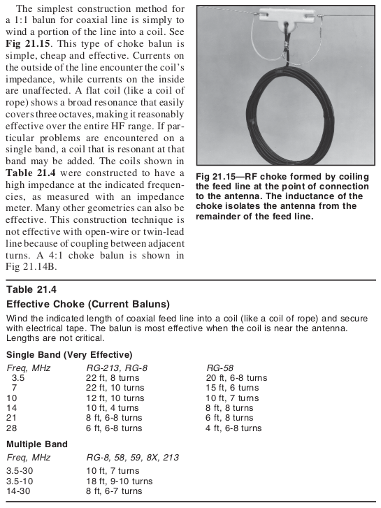
To prevent RF from getting back into the shack on the outside of the coaxial cable (the unbalanced side), I built a 1:1 balun (or choke) and installed it at the feed point (center) of the dipole antenna. Here's the description from the 2008 ARRL Handbook:
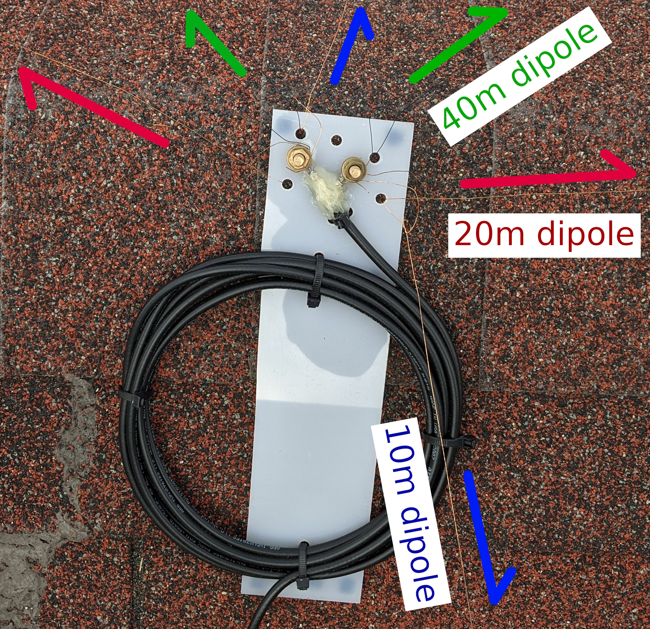
I chose the "3.5-30 MHz Multiple Band" design, using approximately 10 ft of RG-8X in 7 turns. I mounted the coil on a piece of plexiglass to hold the loop together, and also provide a mounting location for screw terminals. The two brass 1/4-20 studs connected to the center conductor and shield allow easy connection and disconnection of individual antenna elements. Brass is mostly copper, so it has good electrical conductivity and doesn't rust.
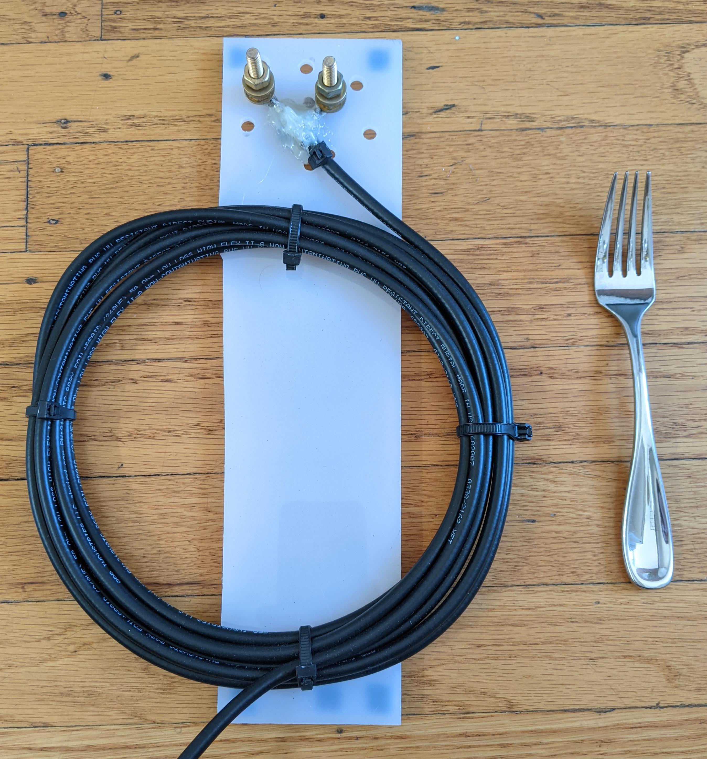
Always make sure to waterproof any RF connectors and termination points. For the transition from coax to the two brass studs, I used hot glue. Water intrusion into the coax is a nasty problem that only surfaces when it's raining hard. After a few days in the sun it dries out and no problems can be found, until the next rainstorm. Rubber feet on the bottom of the plexiglass sheet keep the bolt heads from shorting out on whatever surface this is mounted to.
An alternative to the coil of coax is looping the coax a few times through a ferrite toroid. I didn't have any on hand for this project, so I used the coil of coax.
Fan/Parallel Dipole
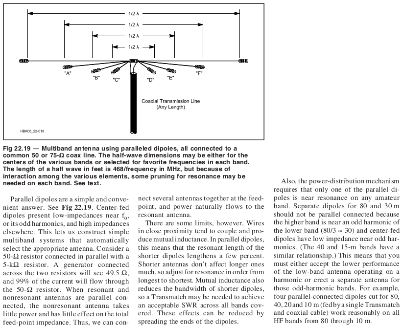
The design of the multi-band fan/parallel dipole is very simple. Fundamentally, it's just separate dipoles fed from the same point. The different elements interact with each other a bit, so if you have the space and don't really care where the radiation is directed, you can orient the elements 90 degrees from each other to reduce coupling. Here is the description from the 2008 ARRL Handbook:
For the calculated lengths of each element, you can just use the standard dipole formula. Here is the standard dipole length equation from the 2008 ARRL Handbook:
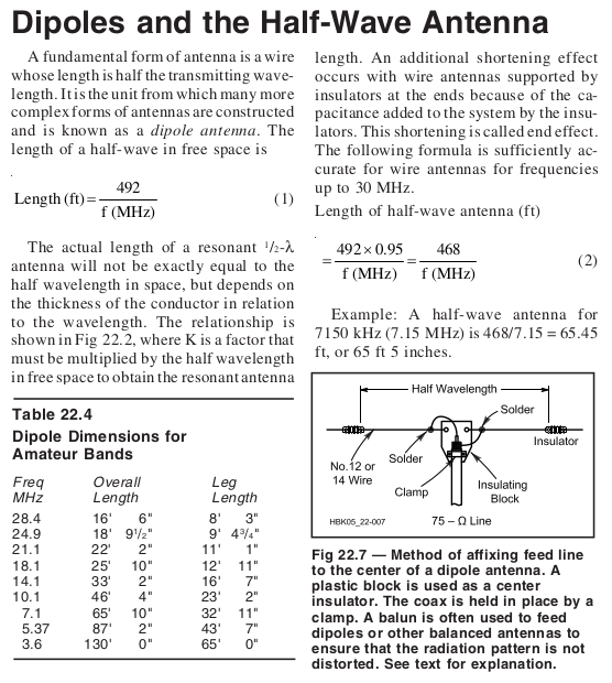
When building a homemade antenna, always make the elements a 5% longer than the calculations show, then shorten them up in the tuning process. It's easier to trim an element (or piece of wood!) down to length than trying to add another section. To make this antenna as unobtrusive as possible, I used 30 gauge enameled wire from the craft store. Remember to scrape off the clear or colored enamel where you want an electrical or RF connection. Very thin wire (like this) means that the resonant bandwidth is pretty narrow, as we will see below.
In the future, if I wanted to add another element for a different band, I can just loosen the bolt and connect up another dipole element. As mentioned in the text, dipole antennas are also resonant at their third harmonic. The 40 meter (7 MHz) dipole is also resonant at 21 MHz, which is the 15 meter amateur radio band. So when adding another band to this fan dipole, care should be taken not to add elements that are odd-harmonics of existing elements (80 meters and 30 meters, for example).
Antenna Measurement
The best way to measure a homemade antenna is to use either an antenna analyzer or NanoVNA. Both of these devices will show you return loss or SWR in your band of interest, and you can see in real-time how shortening the antenna elements changes the resonant frequency. You can also use a power meter, but you are limited to the transmit bands of your radio, so it will be difficult to find resonances outside the amateur bands.
Measuring the S11 return loss of this antenna shows that I did a pretty good job tuning it. I used a FieldFox network analyzer, so in this graph lower is better, meaning that more energy is being radiated out into the air (which is what we want).
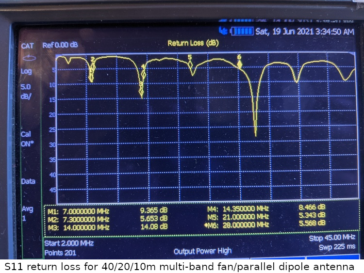
You can see the resonance of the 40 meter band (7 MHz) between markers 1 and 2, with between 9.3 and 5.6 dB of return loss. The 20 meter band (14 MHz) is even better, with more than 8 dB of return loss across the band. I cut the 10 meter dipole a bit too short, so the resonant frequency is a bit above marker 6 at 30 MHz. But this is OK, as the built-in antenna tuner on the Kenwood TS-2000 can tune this no problem.
As mentioned above, the 40 meter dipole is resonant at 15 meters, and this shows a return loss of better than 5dB (marker 5) in this band. There is a formula to convert return loss into SWR, but since everything here is 50 ohms I just use a table.